
At the end of this lesson-
- You will be able to explain logic gate.
- You will be able to describe the types of logic gate.
- You will be able to describe the basic gates in details.
Go For Bangla Version
Logic gates:
A logic gate is a basic building block of a digital circuit, which is used to implement a Boolean function. It is an electronic circuit which makes logical decisions based on the combination of digital signals present on its inputs. It is an electronic circuit having one or more than one inputs and only one output.
Types of Logic gates:
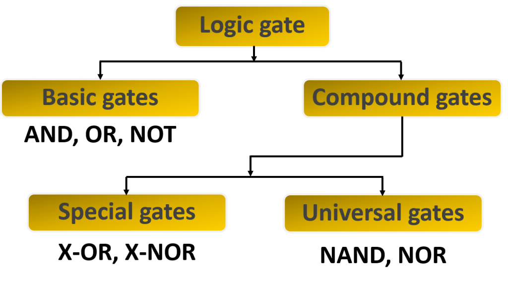
Basic Gates:
Basic gates which implement the basic operation of Boolean Algebra. All compound gates and any logic circuit can be implemented using basic gates. There are three types of basic gates in digital electronics. They are-
- OR Gate
- AND Gate
- NOT Gate
OR Gate:
OR Gate is a gate of logical addition. That is, the gate used to perform logical additions in Boolean algebra is called OR gate. The OR gate has two or more input lines and only one output line. Since OR Gate is a gate of logical addition, it follows the rules of logical addition. This means output goes HIGH to a logic level 1 only when any of its inputs is HIGH. In other words for a logic OR gate, ALL “LOW” inputs will give a “LOW”, logic level “0” output.
The switches of OR gate’s switching circuit are connected in parallel connection. As a result, if one of the switches is ON(1) the bulb will be lighten.
2-input OR Gate:

3-input OR Gate:

AND Gate:
AND Gate is a gate of logical multiplication. That is, the gate used to perform logical multiplication in Boolean algebra is called AND gate. The AND gate has two or more input lines and only one output line. Since AND Gate is a gate of logical multiplication, it follows the rules of logical multiplication. This means output goes HIGH to a logic level 1 only when all of its inputs are HIGH. In other words for a logic AND gate, any LOW input will give a LOW output.
The switches of AND gate’s switching circuit are connected in series connection. As a result, if one of the switches is OFF(0) the bulb will not be lighten.
2-input AND Gate:

3-input AND Gate:

NOT Gate:
NOT Gate is a gate of logical inversion/complement and is often referred to as an Inverting Buffer or simply an Inverter. That is, the gate used to perform logical inversion/complement in Boolean algebra is called NOT gate. The NOT gate has only one input line and one output line. Since NOT Gate is a gate of logical inversion/complement, it follows the rules of logical logical inversion/complement. This means output goes HIGH to a logic level 1 when its input is LOW. and output goes LOW to a logic level 0 when its input is HIGH.
The switch of NOT gate’s switching circuit is connected with the bulb in parallel connection. As a result, Bulb will be lighten if switch is OFF But Bulb will not be lighten if switch is ON.

Lesson Evaluation-
Knowledge Based Questions:
a. What is logic gate?
a. What is basic logic gate?
Comprehension Based Questions:
b. “If any one of the inputs is false in AND gate, Output becomes false”- Explain.
b. ‘AND gate indicates logical multiplication’- Explain.
b. “If any one of the inputs is true in OR gate, Output becomes true”- Explain.
b. ‘OR gate indicates logical addition’- Explain.
b. ‘Output of a logic gate is inverse to the given input’ -Explain.
Creative Questions:
According to the stem answer the following questions:
Mr. Atiq uses a bed switch to run the fan in his bedroom. He turned off the bed switch as he was feeling cold. As a result, the fan was shut down.The fan was switched off even though the fan had a switch on, he thought how it is possible!
According to the stem answer the following questions:
Two doors must be crossed to enter the room where the important files of a bank are kept. When you switch one of the two switches on the first door, the door opens but the door is not opened when two switches turned on or off at once. The door is not opened if there is a switch off in the second door.
c) Explain the logic gate that indicates the second door of the stem.
According to the stem answer the following questions:

c) Draw the logic symbol and create the truth table of the fig-1.
d) Draw the logic symbol and create the truth table of the fig-2 for three inputs.
According to the stem answer the following questions:

c) Truth table-1 is similar to which gate? describe.
Multiple Choice Questions:
1. Output of AND gate will be 1 if —
a) All inputs are 0 b) Any one inputs is 0 c) All inputs are 1 d) Any one inputs is 1
According to the stem answer the question No 2 and 3:
| Truth Table | ||
| A | B | F |
| 0 | 0 | 0 |
| 0 | 1 | 1 |
| 1 | 0 | 1 |
| 1 | 1 | 1 |
2. The truth table indicates which gate?
a) AND b) NAND c) OR d) NOR
3. The truth table indicates which Boolean function?
a) F=A.B b) F=(A.B)´ c) F=A+B d) F=(A+B)´
4. How many basic gates are in digital circuit?
a) 2 b) 3 c) 4 d) 5
5. The basic logic gate are-
i.NOR ii. AND iii. NOT
Which one is correct?
a) i & ii b) i & iii c) ii & iii d) i, ii & iii
6. If any one inputs is 1 in OR gate, then output will be —
a) 0 b) 10 c) 1 d) 11
7. Output of OR gate is equal to logical—- of inputs.
a) addition b) multiplication c) division d) subtraction
8. Output of AND gate is equal to logical—- of inputs.
a) addition b) multiplication c) division d) subtraction
9. Output of OR gate will be 1 if —
i. All inputs are 1 ii. Any one inputs is 1 iii. All inputs are 0
Which one is correct?
a) i & ii b) i & iii c) ii & iii d) i, ii & iii
10. Output of OR gate will be 0 if —
a) All inputs are 0 b) Any one inputs is 0 c) All inputs are 1 d) Any one inputs is 1
11. Output of AND gate will be 0 if —
i. All inputs are 1 ii. Any one inputs is 0 iii. All inputs are 0
Which one is correct?
a) i & ii b) i & iii c) ii & iii d) i, ii & iii
12. In which gate there is an input and an output?
a) AND b) NAND c) OR d) NOT
Written by,
- Mizanur Rahman (Mizan)
- Lecturer in ICT, Shaheed Bir Uttam Lt. Anwar Girls’ College , Dhaka Cantonment
- Founder & Author at www.edupointbd.com
- Software Engineer at mands IT
- Former Lecturer in ICT, Cambrian College, Dhaka
- Contact: 01724351470