
At the end of this lesson-
1. You will be able to explain encoder.
2. You will be able to describe the uses of encoder.
3. You will be able to explain decoder.
4. You will be able to describe the uses of decoder.
5. You will be able to differentiate encoder and decoder.
Go for Bangla Version
What is Encoder?
An Encoder is a combinational circuit that produces a binary code equivalent to the input, which is active High. In other words, Encoder is a circuit which converts the analog signal into the digital signal. Encoders are digital circuit used for encoding.
Characteristics of Encoder:
- It has maximum of 2n input lines and ‘n’ output lines.
- It encodes 2n input lines with ‘n’ bits.
- It performs the reverse operation of Decoder.
- At any time, only one of inputs can be ‘1’ in order to get the respective binary code at the output and rest of the inputs are zero(0).
- It is used in input system like Keyboards.

Fig: Block diagram of Encoder
4-to-2 Line Encoder:
Let 4 to 2 Encoder has four inputs D0, D1, D2 & D3 and two outputs X & Y. The block diagram of 4 to 2 Encoder is shown in the following figure-
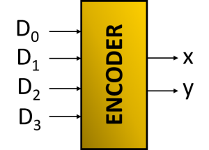
Fig: Block diagram of 4 to 2 Line Encoder
At any time, only one of these 4 inputs can be ‘1’ in order to get the respective binary code at the output. The Truth table of 4 to 2 encoder is shown below.
 Fig: Truth table of 4 to 2 Line Encoder
From Truth table, we can write the Boolean functions for each output as
We can implement the above two Boolean functions by using two input OR gates. The circuit diagram of 4 to 2 encoder is shown in the following figure-

Fig: Circuit of 4 to 2 Line Encoder
The above circuit diagram contains two OR gates. These OR gates encode the four inputs with two bits.
8-to-3 line encoder:
Octal to binary Encoder has eight inputs, D0 to D7 and three outputs X, Y & Z. Octal to binary encoder is nothing but 8 to 3 encoder. The block diagram of octal to binary Encoder is shown in the following figure.
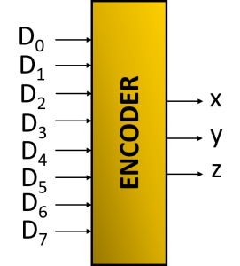
Fig: Block diagram of 8 to 3 Line Encoder
At any time, only one of these eight inputs can be ‘1’ in order to get the respective binary code. The Truth table of octal to binary encoder is shown below.

Fig: Truth table of 8 to 3 Line Encoder
From Truth table, we can write the Boolean functions for each output as
X = D4+D5+D6+D7
Y = D2+D3+D6+D7
Z = D1+D3+D5+D7
We can implement the above Boolean functions by using four input OR gates. The circuit diagram of octal to binary encoder is shown in the following figure-

Fig: Circuit of 8 to 3 Line Encoder
The above circuit diagram contains three 4-input OR gates. These OR gates encode the eight inputs with three bits.
Drawbacks of Encoder
- There is an ambiguity, when all inputs of encoder are equal to zero.
- If more than one input is active High, then the encoder produces an output, which may not be the correct code.
So, to overcome these difficulties, we should assign priorities to each input of encoder. Then, the output of encoder will be the code corresponding to the active High inputs, which has higher priority.
Uses of Encoders
- Encoders are very common electronic circuits used in all digital systems.
- Encoders are used to translate the decimal values to the binary in order to perform the binary functions such as addition, subtraction, multiplication, etc.
- Other applications especially for Priority Encoders may include detecting interrupts in microprocessor applications.
What is Decoder?
Decoder is a combinational circuit that converts binary code or binary information into human understandable format.
In other word, Decoder is a combinational circuit which converts the digital signal into analog signal. Its input will be in digital form while the output will be a continuous sine wave or analog wave. Decoders are digital circuit which are used for decoding.
Characteristics of Decoder:
- It has ‘n’ input lines and maximum of 2n output lines.
- It performs the reverse operation of Encoder.
- At any time, only one of outputs can be ‘1’ and rest of the outputs are zero(0).
- It is used in output system like display units.

Fig: Block diagram of Decoder
2-to-4 Line Decoder
Let 2 to 4 Decoder has two inputs X & Y and four outputs D0, D1, D2 & D3. The block diagram of 2 to 4 decoder is shown in the following figure-
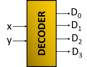
Fig: Block diagram of 2 to 4 Line Decoder
One of these four outputs will be ‘1’ for each combination of inputs. The Truth table of 2 to 4 decoder is shown below-

Fig: Truth table of 2 to 4 Line Decoder
From Truth table, we can write the Boolean functions using SOP method for each output as-


Therefore, the outputs of 2 to 4 decoder are nothing but the min terms of two input variables X & Y.
3-to-8 line decoder
Let 3 to 8 Decoder has three inputs X , Y & Z and eight outputs D0 to D7. The block diagram of 3 to 8 decoder is shown in the following figure-
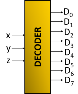
Fig: Block diagram of 3 to 8 Line Decoder
One of these eight outputs will be ‘1’ for each combination of inputs. The Truth table of 3 to 8 decoder is shown below-

Fig: Truth table of 3 to 8 Line Decoder
From Truth table, we can write the Boolean functions for each output as-

The circuit diagram of 3 to 8 decoder is shown in the following figure-

Fig: Circuit of 3 to 8 Line Decoder
Uses of Decoders:
- They are used in a wide variety of applications, including data multiplexing and data demultiplexing
- It is used in seven segment displays
- It is used as address decoders for memory and port-mapped I/O.
- Used for converting binary number into equivalent decimal number.
Difference Between Encoder and Decoder
|
Encoder |
Decoder |
| Encoder is a combinational circuit that converts input signals into binary code. | Decoder is a combinational circuit that converts binary code into human understandable format. |
| There are 2n input lines and n output lines in the encoder. | There are n input lines and 2n output lines in the decoder. |
| Encoders are connected to input devices. | Decoders are connected to output devices. |
| In encoder, the basic logic element is OR gate. | In decoder, the basic logic element is AND gate along with the NOT gate. |
| Encoders are present at the transmitting end. | Decoders are present at the receiving end. |
Lesson Evaluation-
Knowledge Based Questions:
a. What is Encoder?
a. What is Decoder?
Comprehension Based Questions:
b. Explain the circuit that converts human comprehensible language into machine comprehensible language.
b. Why Encoder is used in input devices? explain
b. Explain the circuit that converts machine comprehensible language into human comprehensible language.
b. Why Decoder is used in output devices? explain.
b. “Encoder is the inverse of the decoder”- Explain.
Creative Questions:
According to the stem answer the following questions:

c) Identify the fig-1 and draw the truth table and logic circuit.
d) Which figure is very essential to convert machine code into human understandable symbol? Analyze.
According to the stem answer the following questions:

c) Explain fig-2 for n=2.
d) Draw the truth table and logic circuit of fig-1 for n=3 and analyze that it can convert maximum 8 symbols into machine code.
Multiple Choice Questions:
1. How many minimum output lines are in en Encoder of 40 input lines?
a) 3 b) 4 c) 5 d) 6
2. How many basic logic gates are needed to implement a 4 to 2 line encoder?
a) 2 b) 4 c) 6 d) 8
3. How many basic logic gates are needed to implement a 8 to 3 line encoder?
a) 2 b) 4 c) 6 d) 8
4. Which one is encoder circuit?
a) 8 to 3 line b) 3 to 8 line c) 3 to 9 line d) 2 to 16 line
5. The basic gates used in encoder circuit are-
i. AND ii. OR iii. NOT
Which one is correct?
a) i & ii b) i & iii c) ii & iii d) i, ii & iii
6. Encoder is one kind of circuit which has-
i. n output lines ii. 2n input lines iii. 2n input lines
Which one is correct?
a) i & ii b) i & iii c) ii & iii d) i, ii & iii
7. Which one is inverse of encoder?
a) Multiplexer b) Adder c) Register d) Decoder
8. How many minimum input lines are in a decoder of 48 output lines?
a) 3 b) 4 c) 5 d) 6
9. How many basic logic gates are needed to implement a 2 to 4 line decoder?
a) 2 b) 4 c) 6 d) 8
10. Which one is decoder circuit?
a) 3 to 8 line b) 8 to 3 line c) 1 to 9 line d) 2 to 16 line
11. The basic gates used in decoder circuit are-
i. AND ii. OR iii. NOT
Which one is correct?
a) i & ii b) i & iii c) ii & iii d) i, ii & iii
12. Decoder ia a kind of circuit which has-
i. n input lines ii. 2n output lines iii. 2n output lines
Which one is correct?
a) i & ii b) i & iii c) ii & iii d) i, ii & iii
Written by,
- Mizanur Rahman (Mizan)
- Lecturer in ICT, Shaheed Bir Uttam Lt. Anwar Girls’ College , Dhaka Cantonment
- Founder & Author at www.edupointbd.com
- Software Engineer at mands IT
- Former Lecturer in ICT, Cambrian College, Dhaka
- Contact: 01724351470
